I have a cheap MechanicalEagle Z-77 keyboard.
I’d like to replace the wired USB A cable with a USB-C port.
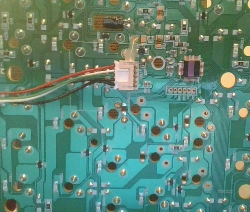
when I open it up, I see the cable is attached like this, with wire colors from the top: red white green black black:
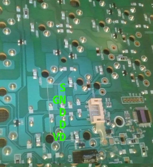
When unclipped, I have this, the 5 pins being labeled “S GN D D VD”:
I find some tutorials about how to do a similar job with soldering. I don’t know how to solder and there is a clip. Can I purchase a USB-C port that will clip into this?
I can’t figure out the name of what this component would be called.
I see some mentioning about resistance and capacitors. I don’t know about these things. What if anything do I need to find out? I don’t know if the info in the soldering tutorials applies the same?
Obviously I am very novice on this topic. If I am missing anything please advise and I will attempt to fill it in.
Here is same device on amazon: https://www.amazon.com/Mechanical-Keyboard-Tenkeyless-Professional-Office-Black/dp/B07ZH7569D
Thank you!
Looks like this might work: https://www.aliexpress.com/item/1005005094002506.html
Do you think it matters that the wire colors are in the opposite order?
In either case, thanks this gets me closer.
It’s not in the opposite order, it’s just flipped around in the photo lol.
Do you think so? the letters are the right way up on the USB-C end. Here is how my existing cable looks in comparison:
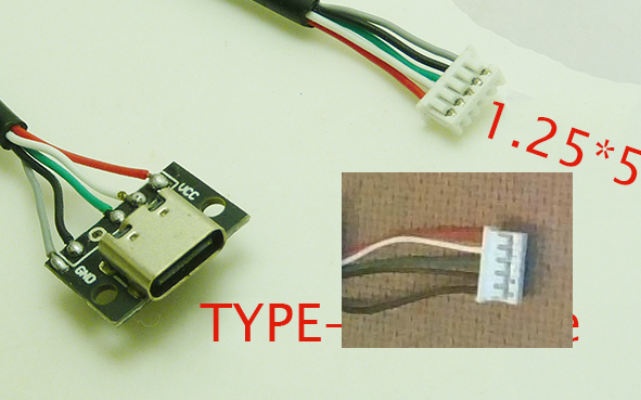
The description lists the letters as VCC, D -, D+, GND, SG.
Electrons don’t care which way the letters are facing
a long as the letters don’t type upside down
If the wires are indeed arranged in the wrong order, but would otherwise be work, popping the individual sockets out and rearranging them is actually quite easy. You just need to either pry the little plastic tabs from the the outside or stick a sewing needle inside, and they should slide out fairly easily. If implementing the sewing needle, it often bends the little metal tab out of the way, and you’ll want to tweak it back with the needle before reinserting in the right slot.
OK thanks! It sort of looks like it would be possible but I didn’t want to go too aggressively at the existing cable until I have a replacement.
The aliexpress seller linked above repeats “The Line Sequence Needs To Be Changed” several times in the description. Maybe this is what that means?
It’s always hard to decipher poor English, but that does seem possible. If you have a multimeter, plugging the socket into a cable would at least allow you to verify the ground and +5v easily. The data etc pins should be doable too, by using a USB A to C cable, and doing a continuity check to the pins inside the USB A side, which would be easy to look up reliably.
As far as swapping the wires around in the plug, that’s one of the easiest plugs to do it with. If you do need to, you’ll be able to.
Yep that should work.
If you’re in the US, I would go for this instead: https://divinikey.com/collections/accessories/products/geon-unified-daughterboard?variant=40438999056449
why is it better?
Shipping will be faster, and you’d be supporting people who make open hardware.
ack shipping is >CA$30. maybe there is a local distributor.
Yeah gave up on some stuff because of the shipping price being more than the actual item price.
It’s so weird how different shipping/distribution can be for different kinds of things. Keyboard-type stuff seems to suffer from it a lot. Even my favorite brand keychron, which seems like a legit business selling at low/mid price, only lists a tiny number of their items on amazon.ca. Buying direct from their website or aliexpress adds a big shipping charge.
Understood, thanks. I will keep in mind. Not in the US so sometimes shipping can be too much on these shopify stores for just 1 item but I will get from here if reasonable.
deleted by creator
At first glance it should “probably work”.
The colours seem to follow the USB standard - red=+5V, black=GND, green=Data+ and white=Data-.\ Not sure why there are two black wires, maybe one’s for the shielding.
To be on the safe side I’d still disconnect the cable and measure from the plug on the photo to the USB plug on the other end.The more exterior black wire is thicker than the other ones. You can’t really see it in the photos. I am thinking it is the same as the grey wire labeled as ground in the AE pic.
What am I measuring? The white box that clips in is exactly 1cm. All these connectors (which I believe are called JST) with 5 pins are labeled as being “1.25” but I can’t tell if that’s dimensional. But what else would it be? I can’t find any that are 1cm.
To find a matching connector you’d normally measure the distance between the pins, at least within the same family of connectors. In this case there are so many similar yet subtly different connectors though, I’m not sure you’ll find the correct one. At any rate, soldering would probably be easiest (even if it’s just aoldering the wires together).
There may be another approach though. With this type of connector, the pins are normally crimped onto the wire and then stuck inside the plastic case. You could buy a few connectors that look like they might fit, remove the pins (use a small tool such as a 0.5mm screwdriver) and try inserting the pins into the case of the original connector in the correct order.
Edit: the thick black wire (original) and the grey one (USB-C connector) should be the same.
Thanks!
I think I miiight have found an exact match: https://www.aliexpress.com/item/1005005073296395.html Not sure what a waterproof USB port is used for but it should do the trick. I’ll buy a few other connectors of similar size to hedge my bets and do as you say if this one doesn’t quite fit.
Looks like I’ll be starting a new plastic compartment container…
So, the issue is you don’t want to solder some cables together? Then just buy these Heat Shrink Self-Solder Butt Splice Connectors.
I mean if I’m going to buy component for the purpose, and there is a clip type thing on the board already, it seems like just obtaining the correct part would be the thing to do if possible. Rather than buying the wrong piece, dismantling the device further and possibly breaking it in the process. (It is really cheap and flimsy.) I’ve spliced things but that’s like more something to do when salvaging or putting something together from what’s on hand.
Neat little gizmos though I’ll file it away for another project perhaps.
